Modelling the World …

to improve it through software. In strive for rigour of science and relevance to engineering.
Latest posts:

Stuff on practical software modelling, like The Killer Application of SwM, the topics of Adjacent Rooms, The Use Case trade-off,

Some epistemic/ ontological foundations of modelling, like General Model Theory by Herbert Stachowiak, the theory of Technical/ Computational Artefacts,

Some logic/ mathematical basics of modelling, like the formal interpretation of relational models, Abstraction by Subsumption, or the merits of Formal Concept Analysis.

Or simply some oldies but goldies?

Opinions always welcome.
So long
|=

Posted in Applications (relevance), Foundations (rigour), Series | Tagged , , , , , , , , , | Leave a comment

Artefacts of logic Intention

Software engineering, as a discipline, could benefit from a more rigorous grounding in Philosophy, e.g., by referring to the concept of “computational artefact” [T]:

Logic Machines

ToasterLet us think of a toaster simply as a machine in which you put in a slice of fluffy bread, push down the lever and take out a slice of toasted bread. In terms of logic, you perform an AND operation, since without both putting in the bread (B) and pushing the lever (L), you take out nothing. So, from the pure perspective of logic, we could describe the toaster as a machine computing  B ∧ L . This could make the toaster a suitable device for use as a stock market advisor. Say, the rule is: buy when the price is at 13 and the sun shines. We can implement this with our toaster by putting in bread if the sun shines and pushing the lever each time the price hits 13. Therefore, each time a slice of toasted bread pops out, we know that this is the time to buy. [P]

Notice, that in the former case, despite our logic perspective, we still use the toaster for its physical output: toasted bread. In the latter case we are purely considering its logical result: stating either true or false.

Furthermore, when the purpose is solely to produce logical results, physical outcomes are merely annoying by-products, which has led us to build machines based on metal strips, relays, transistors, integrated circuits and so on, that produce just small amounts of heat, noise, etc., instead of piles of toasted bread.

Logic Expressions

In strive for our main interest, that of the relationship between Computational Artefacts and Software Requirements, we next look at ways of describing the intention behind such a logic machine. As we already know, intention is not only expressed in terms of input/output pairs, but also by formulas. However, why should we do this? What are the advantages of stating an intention in a language over expressing it as cases?

For instance, we could take these inputs (the ones with output 1)

(0, 1, 1), (1, 0, 0), (1, 1, 1)

and rewrite them as a propositional formula

(¬A ∧ B ∧ C) ∨ (¬A ∧ B ∧ -C) ∨ (A ∧ B ∧ C)

So, what have we gained? At first glance, we achieved the same in a more bloated language. However, propositional language allows us to rewrite the formula as

B ∧ (A ∨ C)

which may be closer to the way in which certain readers prefer to think of it. This way, the choice of an appropriate perspective fosters understanding among stakeholders, which is, by the way, an important, although often neglected, contribution of requirements analysis. Moreover, here in our simple world, the language allows us to formally prove the correspondence between the requirements and the design, when the latter namely, the program, is also written as a propositional formula. These considerations are heading towards formal methods, a subject area highly important in specialized domains such as safety critical systems, but with limited relevance (at least in its ‘heavy weight’ guises) for the greatest proportion of software development. [Z]

Summing up, we used a very elementary setting of machines built for logic purposes and provided a first insight into various ways of expressing the underlying intentions. Here, the intangible concept of understanding may play a central role for requirements analysis. Lots more to muse about. So, stay tuned.

Opinions welcome,
|=

[T] As discussed in:
R. Turner (2018) “Computational Artifacts (Theory and Applications of Computability)”
Springer Berlin Heidelberg
DOI 10.1007/978-3-662-55565-1

[P] For a broader account on what it takes for a physical system to perform a given computation and for a computation to be implemented in a physical system, see:
G. Piccinini (2017) “Computation in Physical Systems”
in The Stanford Encyclopedia of Philosophy, Summer 2017 Edition
Link: Computation in Physical Systems

[Z] For lightweight formal methods, see for example:
A. Zamansky, M. Spichkova, G. Rodríguez-Navas, P. Herrmann, J.O. Blech (2018) “Towards Classification of Lightweight Formal Methods”
ArXvir abs/1807.01923

Previous posts:
2. Computational Artefacts and Software Requirements
1. Technical Artefacts and Software Requirements

Posted in Epistemology, Requirements | Tagged , , , , , , , , , , , , , , , , , | 2 Comments

The Killer Application of Software Modelling

So, you have built a gorgeous model of your software requirements or architecture? Now what to do with it? Many people look for benefits by automating certain aspects of modelling, like checking or transformation. Although this is an intriguing area with huge potential, IMHO the real killer application of modelling lies in a completely different aspect. From my own experience as a business analyst (BA) in quite a number of IT projects I would say: the killer application of a model in software development is talking about it.

Now, “talking about it” sounds simple at first. However, have you ever tried to discuss your ideas with somebody who has a completely different underlying model of how to think of the situation? Quite often it goes like this: I say “” and two hours later, after an exhausting debate, we find out that “” are actually the same, just seen from a different angle. Sounds familiar? And even if our opinions really are contradictory, we still need a common ground if we are to compare them and argue about them. This is what a common underlying model can provide.

Nowadays, software projects are quite heterogeneously staffed, since, for example, there may be a need to scale up the number of people within a short period, special skills may be temporarily required or the project may be affected by a general reorganization. Thus, professionals with different roles, experiences and schools (of thinking) must find a common ground from which to discuss issues such as the business domain, applications of the technology and how to collaborate. This common ground can range talking modelsfrom attaching accepted and meaningful names to objects and relations in the business domain so that they can easily be referred to, through defining appropriate abstraction layers for discussing and deciding on technical architecture, to agreeing on basic notions, such as what is a requirement at all, where does the biz domain model end and the technical architecture start and what are the consequences for project roles and responsibilities. And it doesn’t matter what some book or standard says. In the end, the project itself should decide which concepts or approaches to adopt or to define.

Despite the fact that models of requirements, architectures or the software development process itself can be of great use, the way these models are actually used in software projects varies largely. It ranges from horror scenarios, like posterior documentation or ending up in some abandoned folder, to highly beneficial usages forming a basis for common understanding, debate and decisions, where people really “speak model”.

So, there’s a lot to find out, like:
1. One size doesn’t fit all: classifications of model users
2. Thinking about “talking about it”: classification of communication/ collaboration scenarios involving models
3. How can we tell good models from bad models (for communication purposes)?
4. How fit are current modelling languages for the above scenarios, and how could they be improved?
5. How can we make software development people really adopt a model-based collaboration?

So long,
|=

PS: More on practical software modelling:

Posted in Requirements, Software_Engineering | Tagged , , , , , , , , , , , , , | 1 Comment

A simple relational Model

Let’s recapture some modelling basics:

Some Dia

What does a diagram like (Some Dia) say, in terms of logic?

Relations a b c dLets call the “->” relation R, obviously there are two elements where one is R-related to the other, we express this with two variables x and y, as shown in figure (a), by
(1) x R y

Next, we want to assume that the diagram shows all R-relationships of its contained elements, and thus we must exclude cases like (b) by
(2) ¬yRx ∧ ¬xRx ∧ ¬yRy

Moreover, we want to express that we have at least two elements by
(3) x ≠ y

Finally we assume the diagram to cover the whole model, i.e. there are no other elements, by
(4) z x=z ∨ y=z

Thus, all together we get
(5) x, y (1) ∧ (2) ∧ (3) ∧ (4)

(5) describes (some Dia) structurally, i.e. up to isomorphism. Additionally, we could give the elements a material meaning, say a certain Person (x) drives (R) a certain Car (y). (see Unambiguous Models)

So long
|=

PS
Describing single structures is usually not enough in modelling. What we want is to model sets of structures like every Person drives at least one car.

Posted in Foundations (rigour), Software_Engineering | Tagged , , , , , , , , , , , , , , | 1 Comment

Categories of semantic Models by Stachowiak

In addition to former excerpts of Herbert Stachowiak’s 1973 book “Allgemeine Modelltheorie” (General Model Theory) here are some brief examples from the part on semiological (semological) classification of semantic models (chapter 2.3.2.3).

Semantic vs non-semantic Models

Prior to the subsequent ordering, Stachowiak distinguishes semantic from graphical/technical models. Semantic models are models of perception and thinking expressed by combinations of conventionalized signs. Examples of graphical/ technical models are viewable and graspable models like photographs, diagrams, function graphs; globes, crash test dummies, lab rats etc.

Moreover, following the linguistic separation of expressions of emotions (emotional semantic models) and thoughts (cognitive semantic models) by A. Noreen, Stachowiak deals only with the latter considering the former not to be part of the theory at all.

Kinds of semantic Models

These cognitive semantic models can now be separated into the following categories, here represented by examples:

  • allocative e.g. “Hello, you!”
  • optative e.g. “Have a nice trip!”, “Wouldn’t it be nice …”
  • imperative (order) e.g. “Move over!”
  • interrogative (question) e.g. “What’s you name?”
  • narrative (statement)
    • pre-scientific declarative e.g. “You can get it if you really want”
    • poetical e.g. “The nightingale, the organ of delight”, “Ready to drink wine, with a cherry blossom”
    • metaphysical as biomorphic (e.g. creation of the earth as egg of a prehistoric bird), technomorphic (e.g. canopy (sky), “pushing up the daisies”) or sociomorphic (e.g. willpower as police of the soul)
    • scientific
      • formal (formal science): e.g. expressions in language of first order logic and mathematical structures satisfying them. [see any textbook on mathematical logic]
      • empirical-theoretical (empirical science): structure of real world objects satisfying formal axioms [basically, extraction of formulas from (probably very very difficult) word problems]
      • operative and prospective: empirical models with objects changing (esp. over time) [see any imperative programming language]

Notice that Stachowiak has described these categories in much greater detail, and this is just a first brief overview. The examples are translated very liberally.

So long
|=

PS
The category of empirical-theoretical models, elementary to all kinds of engineering, is covered in more detail in Stachowiak on semantic Requirements Modelling

More on Stachowiak: Herbert Stachowiak postings

Posted in Epistemology, Herbert Stachowiak, Requirements | Tagged , , , , , , , , , , , , , , , , | Leave a comment

Software Requirements Analysis: From the Art of Tidying Up to the Art of Abstraction

Requirements analysis is more than just tidying up, it’s about understanding the complexity of structures. An explanation inspired by the art of Ursus Wehrli:

Is Requirements Analysis just a kind of Tidying Up?

Recently I discussed with some project responsibles, the option to use an issue management system (namely JIRA) for gathering software requirements. The people obviously thought of requirements as a big set of snippets, that have to be collected and ordered, very much like a stamp collection. This seems to be a common misunderstanding of the nature of requirements, which can be elucidated nicely by the art of Ursus Wehli.

Ursus Wehrli is a Swiss comedian and artist, who makes books in which he “tidies up” works of art, for example, sorts the elements of a Kandinsky painting by colour and size, or orders the letters of an alphabet soup alphabetically. (more here: NYT)

Why Tidying Up is not enough

Let’s picture this little Wehrli-forgery here, a unjumbled version of a public transport map:

wehrli zürich tidyIt has lines (heavy for city trains, double for long distance), station names and station nodes. So, what is missing? What exactly makes the difference to a complete map? Obviously, it’s the relationships among the map elements that are missing here.

However, since the elements can still be classified and ordered, there must be some relationships left, determined by the elements’ properties. In this kind of representation they are made explicit, such that it becomes easy to ‘query’ e.g. if there is a station named ‘Opfikon’, or what line is the longest. Thus, simplification by ‘tidying up’ also has certain benefits.

Why Managing Relationships is not enough

wehrli zürich relationSo, why not simply add the relationships to the list, as in (Public Transport related)? It defines the relations name to station node, and station node to line, with station nodes identified by numbers 1 to 11.

So, technically all information would be available. However, for humans it’s still too hard to deal with. The relationships are now manageable by the system, but they are not yet expressed in a human-oriented notation. This is why an issue management system (IMS) is not enough to deal with requirements, even if it’s capable of managing relationships. An IMS’ focus is on sorting and grouping things, for example to make a todo-list of requirements, or to support the management of the analysis process.

And why even Visualisation is not enough

wehrli zürich transport mapFor the typical use of a public transport map, a diagram as (Public Transport) is certainly appropriate, i.e. the human understandability can be accomplished simply by choosing an appropriate notation. And even if the lines and stations become just more, we simply can increase the size of the map. However, if the structure gets more complex, i.e. the elements are ‘closer’ related, diagrams quickly become hard to understand. Visualisation scales well concerning size, but not concerning complexity.

Visualisation of relationships is usually what modelling tools are good at. However, as we have seen the tidy perspective has its advantages, too. Thus, beyond visualising the modelling results (i.e. diagrams), modelling tools should provide ‘tidy’ perspectives (like an IMS), in order support the modelling process. In other words, working out models is more than just documenting them.

Abstraction for Analysis

wehrli zürich airportIf things get more complex – just think of a map with a more complex system of stations and lines (trams, etc) – it might become beneficial to create views on the model, e.g. all available lines from the airport, as in figure (Airport Transport), with connecting lines indicated at each station. Similarly, think of a requirements model of a whole software application, decomposed into data, use-case, state, etc. views/ diagrams. This goes beyond visualisation, this is about abstraction. Thus, as compared to the ‘art of tidying up’, choosing appropriate views on a model, in order to understand its complexity, constitutes the ‘art of abstraction’ (so to say).

By the way, this is also what distinguishes modelling from simple drawing tools. (Just in case, the next project wants to do requirements analysis with VISIO)

So long
|=

PS
Notice that additionally to the relations in (Public Transport related) the diagram (Public Transport) contains the coordinates of the stations. Although, they are only schematic, they provide an approximate geographical location information.
PPS
Ursus Wehrli

Posted in Requirements, Software_Engineering | Tagged , , , , , , , , , , , , , , , | 1 Comment

Craftsman or Engineer?

A brief word on a practical software engineering issue:

A lot has been written on the differences between Craftsman and Engineer.  Recently I came across a simple example by Hofstadter & Sander, that nicely shows the basic difference in thinking. We start with a little exercise:

“Draw a square, a rectangle, a rhombus, and a parallelogram.”

Some people draw a solution as in (a), some draw solution (b).  Both are perfectly acceptable in their way:
shapes abstraction

  • With (a) you show your detail knowledge, of how the shapes are defined, s.t. you are able to give a typical example for each class.
  • With (b) you show your ability to abstract, of how the shapes are related to each other, s.t. you are able to give a special case valid for all conditions.

shapes concept lattice and context

The latter is an abstraction by constructing formal concepts, i.e. by deriving the concept (lattice) from the (context). Imho, being able to ‘navigate’ the concept lattice – that of course looks much more complex for real world subject areas – is what separates the thinking of Engineer and Craftsman.

So long
|=

PS
For example, from my personal experience in business analysis I may say, that typically there are lots of people on the expert side with type (a) knowledge, so what they need an analyst (on engineer-level) for, is help them to create type (b) understanding from it.

Posted in Abstract Thinking, Software_Engineering | Tagged , , , , , , , , , , , , , , , , , , | 4 Comments

Reflections on Abstractions: Subsumptions and Omissions

Abstraction Awareness is about deeper understanding of abstraction, a concept so basic to human thinking. Subsequently we provide a simple visualisation of some basic concepts.

In addition to the recent posting Abstractive and Functional Mappings we provide a simple visualisation.  There we defined abstraction by subsumption as a not lhs*-unique mapping, and abstraction by omission as a not lhs-total mapping. This, and the combination of both to an ‘omsumption’ (excuse the word), is illustrated below.

abstraction subsumption omission

So long
|=

* lhs = left hand side

Posted in Mathematics, Reflections on Abstractions | Tagged , , , , , , , , , , , , , | 1 Comment

Reflections on Abstractions: The Use Case trade-off

Loosely collecting examples of abstractions on finite relational structures:

Relational World

relational abstractionIn the posting Adjacent Rooms we had an abstraction as in figure (abstraction by ‘is related’), a mapping with the structural unsatisfactory property to be non-unique on the model-side, e.g. the ‘2’ in the original is mapped to 2 different nodes in the model. However, we also saw an example where this sort of abstraction fits quite well, and thus speaks in favour of the relevance of this kind of abstractional mapping.

Real World

request processinguse cases request processingAnother such example is the abstraction of functionality by Use Cases. Figure (Request Processing) shows a simple process for handling customer requests, that can be of various kinds, like placing an order, a request for product information, or a change of the billing address. Think of the activities as nodes of a graph as above.

Now, the basic idea of a Use Case is to lump together activities such that they form an emergent behaviour (easy to comprehend). In figure (Use Cases) we have three of these. Obviously the Use Cases are overlapping, since e.g. the ‘Dispatch request’ activity is contained in all Use Cases, as well as ‘Send reply’ appears in ‘Update Static data’ as well as in ‘Request Information’ (indicated by the edges among the Use Cases). Thus we get better understandable (emergent) units of functionality, however usually for the price of a non-unique mapping.

Based on the elementary terms of relational structures, this shows the basic trade-off of Use Cases: emergence vs redundancy.

Remarks

  1. The ‘extend’ or ‘include’ relationship in UML are typical elements to address this redundancy issue.
  2. Compare the kind of knowledge gained out of such a formal analysis as above to that you get from common text books on Use Cases. Moreover, seems that some very popular books, don’t address this trade-off at all (!?)

So long
|=

Posted in Mathematics, Reflections on Abstractions, Requirements, Software_Engineering | Tagged , , , , , , , , , , , , , , , | 2 Comments

Reflections on Abstractions: Adjacent Rooms

Loosely collecting examples of abstractions on finite relational structures:

Relational World

Relational abstractionFigure (abstraction by ‘is related’) shows an abstraction by subsuming directly connected nodes in the original into a single node in the model. An edge in the model indicates a common element of its nodes in the original. For example, the nodes 1, 2 become a single node (1, 2) that is related to e.g. node (2, 3) since they have the element 2 in common.

Real World

rooms wallsA practical case of such an abstraction is a structure of walls that is abstracted to rooms with the neighborhood relation, where neighborhood is defined by having a wall in common, as in figure (wall in common). For example, the bath (Ba) has walls in common with the bed room (BR) and the foyer (F).

Remarks

  1. The abstraction takes into account only the relationships of the nodes. No further properties are considered.
  2. The abstraction is total on the original-side and not unique on the model-side.
  3. The model has more nodes than the original. Is this a contradiction to the reduction property of abstraction? I Don’t think so, since a reduction exists from two connected nodes to a single node. Other opinions?

So long
|=

PS
for an informal definition of reduction in the context of models, see Stachowiak

Posted in Abstract Thinking, Reflections on Abstractions | Tagged , , , , , , , , , , , | 7 Comments

Examples of Preterition and Abundance in Modelling

In addition to the earlier posting Stachowiak on Preterition and Abundance in Modelling here are some examples of Preterition and Abundance (also see here for all postings on Stachowiak):

Stachowiak Abundance Preterition Black WhiteIs this a black and white picture? Is this a colour image of a black/ white arrangement or a black/ white image of a coloured arrangement?  In the latter case, even if you want not to express the colour of the Original at all, you have to choose some colour for the image (here, the scale from black to white).

Stachowiak Abduction Use CaseWho triggers the Use Case? In UML the association between actor and use case is not allowed to have a direction. Thus, in order to express that an actor triggers the use case it are sometimes notated on the left hand side. So, the diagram could say that the customer triggers the use case or not. We cannot say, without any further information.

Stachowiak Maza LabyrinthWhat does the graph tell about the maze? The graph inside the maze preserves coordinates and path length. Also in the graph on the right nodes have coordinates and edges have lengths. However, they are not meaningful anymore. They were ‘sacrificed’ for the sake of a certain view.*

Notice that a lot of further questions apply in the graph on the right: does the top element represent the starting point? Is 1-2-4-6-8 a kind of primary path (typical issue in process models)? Is it better to have all edges of equal length, to indicate the abundance?

So far, just a few examples that came to my mind.
|=

*Stachowiak gives a similar example in his book “Allgemeine Modelltheorie”. The book at Google books.

Posted in Epistemology, Herbert Stachowiak, Software_Engineering | Tagged , , , , , , , , , , , , , , , , , , | 5 Comments

Reflections on Abstractions in Relational Structures. The very basic Setting.

Abstraction Awareness is about deeper understanding of abstraction, a concept so basic to human thinking. Subsequently abstraction is discussed by the means of basic Graph Theory and Formal Concept Analysis.

A single unary relation R(x), can simply classify e.g. Naturals in evens and odds. This doesn’t take us very far.  So, they should be enhanced by either adding more unary relations or making the relation 2-ary, 3-ary etc.  Moreover, both can be combined to multiple n-ary relations. However, here we stick with the basic two cases, and adjourn the combined case until ‘later’.

fca-lattice-even-oddMultiple unary relations R(x), S(x), …, can describe complex property structures.  In the theory of Formal Concept Analysis, this is said to be a Context.  Now in order to handle the complexity of such structures by Abstraction, the concept of a Formal Concept proves very helpful.  All Formal Concepts of a structure provide a lattice, which helps us ‘understanding’ the structure.  Thus, in abstractional terms, Classification (by Formal Concepts) implies Generalisation (Concept Lattice). in detail…

graph-mod-cmpA single n-ary relation R(x, y, …), shows how the elements are related to each other.  Graph Theory provides two basic concepts here that describe Abstraction:  A Module (corresponding to the abstractional concept of Classification) lumps together all the nodes, that have the same edges to other nodes, i.e. appear the same to the outside, so to say.  A Component (corresponding to the abstractional concept of Aggregation) groups the nodes, closely connected to each other and loosely connected to the outside, roughly speaking.
Moreover, both, Modules and Components, can be sorted hierarchically, in order to simplify the ‘understanding’ of the structure.  Intuitively, I would call this Generalisation in the case of Modules.  However, for Components, the term ‘composition’ sounds more natural to me. in detail…

It is hoped, that this can provide a very basic setting for a deeper analysis of the nature of Abstraction.  Some questions arise immediately, like ‘how do formal concepts and modules fit together?’ (i.o.w. how can they be generalised?) or ‘what makes modules and components the outstanding concepts for abstraction?’ (i.o.w. what properties define the formal concept of ‘module and component’ in the context of abstraction?) etc.

So long
|=

Posted in Mathematics, Reflections on Abstractions | Tagged , , , , , , , , , , , , , , , , , | 2 Comments

Reflections on Abstractions: Correctness and Completeness

Abstraction Awareness is about deeper understanding of abstraction, a concept so basic to human thinking. Subsequently, in strive for rigour, an earlier post on quality properties of models is compared to basic concepts of mathematical logic.

1. Correct and Complete, simply put

cc-custsysThe former post, gave a brief explanation what correct, complete, etc. means for models, as in the figure.  Where correct meant, no requirement in the model is wrong and thus every solution accepted by the customer (in C) is in accord with the model (in M) and complete is, no requirement in the model is missing and thus every solution according to the model (in M) is also accepted by the customer (in C).

2. The concept of a Formal System

In mathematical logic a formal system (FS) is a triple of a language syntax, a set of axioms and a resolution mechanism, for example, the syntax of first order logic, the axioms of the theory of equivalence relations, and the |- resolution operator, such that theorems can be derived from the axioms.

A structure that obeys such a FS is said to be a model. For example, for my red and white socks, being of equal colour defines an equivalence-relation.

A FS has at least one model if, and only if, it is consistent, i.e. the axioms are not self-contradicting, and thus can be fulfilled.

So, consistency assumed, the axioms define a set of models A, as well as any theorem defines a set of models T, and thus proving a theorem (by the resolution operator) comes down to show that the models of the axioms A are a subset of the models of the theorem T.

3. Correct and Complete, formally put

Now the above situation in a FS seems quite similar to that of a ‘customer system’: instead of written down axioms in some language, we have requirements, ‘hidden inside the head’ of the customer, that we have to explore by stating requirements (theorems). Instead of a resolution mechanism we have the customer itself, as a kind of oracle that answers our questions.

Thus, when a requirement is accepted by the customer it defines a superset of the accepted solutions (models), and hence is said to be correct. Correspondingly, if the requirements altogether define a subset of the accepted solutions (models), they are said to be complete. Thus, correct and complete, ensures that the stated and the accepted solutions are congruent (consistency assumed).

So long
|=

PS
Concerning ambiguity: if there is at most one model for the axioms in the FS, then together with consistency (at least one model), the model is said to be unique up to isomporphy (because maths is a structural science).

Posted in Mathematics, Reflections on Abstractions | Tagged , , , , , , , , , , , , , , , , , , , , , , | Leave a comment

Reflections on Abstractions: Cases vs Models

Abstraction Awareness is about deeper understanding of abstraction, a concept so basic to human thinking. Subsequently abstraction is discussed by the means of basic Finite Model Theory.

All finite relational structures can uniquely be described in First Order Logic (FO) up to isomorphy. This is quite pleasant, since FO is a relatively nice and simple language (for expressing queries, doing proofs, etc). For example, a structure consisting of a 2-elementary alphabet and a binary relation R (see figure) can be characterised by conjunction of the following sentences:
Relation_2x2I
(1) there are exactly 2 elements
(2) for x≠y: R(x,x), R(y,y) holds, R(x,y), R(y,x) doesn’t
where both sentences can be expressed in FO (see here for formalism).

However, another way to characterise R is:
II
(1) as above
(2′) R is reflexive and empty else ( x=y ⇔ R(x,y) )
what is also expressible in FO.

Between the two axiom systems (I) and (II) there is an essential difference: While (I) lists all existing cases in (2), (II) uses the property of reflexivity (2′) to characterise the structure. The latter has certain advantages: it, can be expanded easily for structures of more than 2 elements, and it states a principle that can be understood by humans.

This describes by simple means of basic Finite Model Theory a very important principle in software engineering: modelling properties is more expressive than just collecting cases. This is the reason why test cases can be derived from specifications but not vice versa. Another example is Intentional Programming, addressing that the big picture ‘gets lost’ on the source code level.

Like most things in life, expressing properties by models also comes with a downside: While cases as in (I) can always be expressed in FO, properties in general cannot. For example, for expressing that the alphabet of a structure is always of even size, FO is not expressive enough.

Thus, altogether cases vs models is always a trade-off.

So long
|=

PS for the ‘light’ version, see previous post

Posted in Mathematics, Reflections on Abstractions | Tagged , , , , , , , , , , , , , , , , | Leave a comment

General Model Theory by Stachowiak

In his 1973 book “Allgemeine Modelltheorie” (General Model Theory) Herbert Stachowiak describes the fundamental properties that make a Model.  Unfortunately this is still only available in german language, so I thought why not try a translation of the essential bits:

Fundamental Model Properties

  1. Mapping: Models are always models of something, i.e. mappings from, representations of natural or artificial originals, that can be models themselves.
  2. Reduction: Models in general capture not all attributes of the original represented by them, but rather only those seeming relevant to their model creators and/ or model users.
  3. Pragmatism: Models are not uniquely assigned to their originals per se. They fulfill their replacement function a) for particular – cognitive and/ or acting, model using subjects, b) within particular time intervals and c) restricted to particular mental or actual operations.

Remarks

  1. Mapping: Such originals can evolve in a natural way, be produced technically or can be given somehow else. They can belong to the areas of symbols, the world of ideas and terms, or the physical world. […] Actually, every entity, that can be experienced (more general: ‘built’) by a natural or mechanical cognitive subject, can in this sense be considered an original of one or many models. Originals and models are interpreted here solely as attribute classes [representable by predicate classes], that often achieve the shape of attributive systems [interrelated attributes that constitute a uniform orderly whole]. The concept of mapping coincides with the concept of assigning model attributes to original attributes in the sense of a mathematical (set theoretical, algebraic) mapping.
  2. Reduction: To know once that not all attributes of the original are covered by the corresponding model, as well as which attributes of the original are covered by the model, requires the knowledge of all attributes of the original as well as of the model. This knowledge is present especially in those who created the original as well as the model , i.e. produced it mentally, graphically, technically, linguistically, etc in a reproducible way. Only then an attribute class is determined the way intended by the creator/ user of the original and the model. Here, an attribute class is an aggregation of attributes of the original as well as of the model side, out of the overall unique attribute repertoire. Thus, the original-model comparison is uniquely realisable. […]
  3. Pragmatism: Beyond mapping and reduction the general notion of model needs to be relativised in three ways. Models are not only models of something. They are also models for someone, a human or an artificial model user. At this, they fulfil their function over time, within a time interval. Finally, they are models for a certain purpose. Alternatively this could be expressed as: a pragmatic complete determination of the notion of model has not only to consider the question ‘what of‘ something is a model, but also ‘whom for‘, when, and ‘what for‘ it is a model, wrt. its specific function. […]
  • Stachowiak, Herbert (1973) (in german (DE)). Allgemeine Modelltheorie [General Model Theory]. Springer. ISBN 3-211-81106-0.

Have fun
|=

PS
Part II: Stachowiak’s K-System of Modelling

Posted in Epistemology, Herbert Stachowiak | Tagged , , , , , , , , , , , , , , | 25 Comments

Lecture Notes on Model Thinking I

Some lecture notes/ scribble on Model Thinking by Scott E. Page. Lecture Intro, Part 2: “Intelligent Citizens of the World”:

“George Box: ‘essentially all models are wrong, but some are useful'”

|=: Agree! Just a little everyday-obervation: it’s funny how often people use right/ wrong in the context of abstraction (i.e. models), not realising, without being ‘wrong’ (i.e. loosing details) it would not be a model. Such discussions usually start sth like this:
2 Rects
A:‘These are two rectangles!’ B:‘No, no, these are two essentially different things!’ … (sounds familiar?)

Have fun
|=

PS
Are you a hedgehog or a fox?: Try the quiz on Overcoming Bias
and this is Philip E. Tetlock: Wikipedia

Posted in Abstract Thinking, Model Thinking | Tagged , , , , , , , , , , , , | 17 Comments

Are your Requirements complete?

No Analyst will ever can tell if the requirements are complete, however at least completeness can be approached by systematic analysis. The idea goes roughly like this:

Say you should tell all the Integers between 0 and 11, how would you approach that?
Bad way: “6, 3, 2, 1, 8, 6, 5 – so, that’s it or did I miss one?”
Good way: “1, 2, 3, 4, 5, 6, 7, 8, 9, 10 – bingo!” – for example.

Obviously the point is, to obtain an understanding the structure of the domain. Else it is just collecting facts. Finding appropriate systematics, I’d see mainly in the responsibility of the analyst.
Bad way: “Tell me all the integers between 0 and 11.”
Good way: “What’s the next integer after 0?” etc – for example.

To me this is already a basic application of modeling and its benefits.

Posted in Epistemology, Software_Engineering | Tagged , , , , , , , , , , , | 4 Comments

Why finiteness counts

Becoming aware of Finite Model Theory. Part 1 of n.

You arrive at a hotel, looking for a room. Unfortunately all rooms are occupied. Fortunately the hotel has countably infinite many rooms. So they move the guest of room 1 to room 2, guest of room 2 to room 3 etc so you can check in to room 1. (better don´t unpack your suitcase, in case the next guest arrives)

So compared to the real world the hotel doesn’t have to manage the occupation of its rooms, therefore it has to handle infinity, i.e. if one wants to deal with the above on a scientific level, one must be able to capture the concept of infinity formally.

Finite hotels (as well as ‘finite scientists’) don’t have to care about infinity; therefore they have to deal with the complexity of managing occupation. This can be done by keeping track of the number of empty rooms or by looking up all rooms for an empty one each time a guest arrives. The first approach is space consuming (since they have to write down the number empty rooms somewhere (i.e. space can be a piece of paper)). Instead the second approach requires time to go and check the rooms.

Thus there are two mutually exclusive things that can make occupation management interesting: infinity with all its ‘strange’ effects and the complexity (effort) of keeping track of ‘what’s going on’.

PS
Or how Neil Immerman puts it: “In the history of mathematical logic most interest has concentrated on infinite structures….Yet, the objects computers have and hold are always finite. To study computation we need a theory of finite structures.”

Posted in Mathematics | Tagged , , , , , , , , , , , , , , , | 11 Comments

Artefacts in Technical and Social Contexts

The other day, I was reading “G. Goldkuhl (2013) The IT Artefact: An ensemble of the social and the technical? – A rejoinder”. Here’s what I’ve learned:

Social Artefacts

Goldkuhl points out the non-physical effects that physical artefacts might have:

“Even if artefacts in these theories [of intentionionally creating things] are considered as physical entities, it is important to note that their functions are not restricted to material influence. Other functions as social and aesthetic functions are also acknowledged”

Moreover, artefacts of a non-physical nature might exist:

“Even if an artefact does not need to have a physical existence [according to Lee], it needs to have some separate and enduring existence and it should be brought into existence as a result of some intentional making of humans.”

Hereinafter he focuses on physical artefacts with social influence, “social artefacts” [K], by considering “computational artefacts” [T] in human contexts.


“When looking at ovens, it is their capacity to produce heat that is the essential function. When looking at IT artefacts, the most important trait is their capacity to mediate communication between people
…. 
However, we do not need to put humans inside the boundary of the IT artefact in order to make these artefacts social.”


This, of course, completely ignores the existence of computational artefacts in purely technical contexts, usually referred to as embedded systems. However, the underlying idea in social and technical contexts is pretty much the same: extract the information processing part and embed it as a separate artefact (embedded system) in the overall system.

Embedded Artefacts

Vending Machine

Let us stick with this “embedded” aspect here, as we see it as the main point of the work. We have computational artefacts embedded in a technical and/or social environment. Take, for instance, a vending machine, that has a unit triggering the dispenser and which can process the user input from the key pad. So far, it is the same idea, but how does it stand up to a closer look?

  1. Obviously interfaces to humans and machines are considerably different. Where CA to machine is down to electrical impulses, human CA interaction still requires clumsy devices like keypads, mice, screens etc. But notice that this is a physical aspect of CA, not an informational one.
  2. Machines (only) do as they’re told. Except in case of mechanical defects, machines execute the orders they are given by the CA. However, since there are no such things as pop-up boxes asking “Are you really sure? – Yes, No, Abort”, all circumstances must be considered beforehand.
  3. Humans have common sense (and other problems). Apart from misunderstandings caused by the user interface (i.e., when physical difficulties affect the information processing), unexpected effects can stem from the nature of a human as an information-processing social being.
    On the upside, however, considering information from a CA with human common sense might save us from fooleries like commencing another world war (this has actually happened). [S]

Altogether, we see that CAs in social and technical contexts differ not only in terms of their interfaces:

“It is important to see that social structure (to use this term from Orlikowski & Iacono, 2001) is inscribed into the IT artefact.”

Summing up, the term “embedded system” applies to CAs inside technical as well as social systems. However, a CA in a human context is not just a CA from a machine context with a cuter interface.

Practitioner’s takeaway: Often this social/ technical distinction can tell a lot more about the character of a software project, than just its line of business or technology. Makes it a helpful clarification in every project abstract or summary.

Opinions welcome,
|=

[K] P. Kroes (2012) “Technical Artefacts: Creations of Mind and Matter”
Series: Philosophy of Engineering and Technology (6), Springer Dordrecht
DOI 10.1007/978-94-007-3940-6

[T] As discussed in:
R. Turner (2018) “Computational Artifacts (Theory and Applications of Computability)”
Springer Berlin Heidelberg
DOI 10.1007/978-3-662-55565-1

[S] A great read on this is: B.C Smith (1985) The Limits of Correctness

Previous posts:

  1. Artefacts of logic Intention
  2. Computational Artefacts and Software Requirements
  3. Technical Artefacts and Software Requirements

Posted in Epistemology, Requirements | Tagged , , , , , , , , , , , , | 1 Comment

The Beauty of Theories and Wittgenstein’s Grief

Some brief thoughts, inspired by ‘Theories as Artworks’ in Jiri Benovsky (2021) The Limits of Art:

Scientific theories have the capacity to cause passion, or said and judged to be beautiful (or not). They can be subject to aesthetic judgements, have the capacity to trigger aesthetic experiences and are challenging, both for the artist and the observer.

Now, one can see the beauty solely in the theory itself, as a self-containing thing and might become frustrated when the theory is applied in rough and ambiguous practice. Or is probably just the way the theory touches reality the actually point in which its beauty lies? I found this issue nicely reflected in the 1993 movie “Wittgenstein” by Derek Jarman:

Let me tell you a little story. There was once a young man who dreamed of reducing the world to pure logic. Because he was a very clever young man, he actually managed to do it. When he’d finished his work, he stood back and admired it. It was beautiful. A world purged of imperfection and indeterminacy. Countless acres of gleaming ice stretching to the horizon.

So the clever young man looked around the world he’d created and decided to explore it. He took one step forward and fell flat on his back. You see, he’d forgotten about friction. The ice was smooth and level and stainless. But you couldn’t walk there. So the clever young man sat down and wept bitter tears. But as he grew into a wise old man, he came to understand that roughness and ambiguity aren’t imperfections, they’re what make the world turn.

So, to close with Benovsky again: And, precisely because of the way theories accomplish their purpose, they certainly are “fitted to give a pleasure and satisfaction to the soul”, as Hume puts it.

Beautiful Christmas
|=

Posted in Applications (relevance), Foundations (rigour) | Tagged , , , , , , , , , , , , | 1 Comment

Computational Artefacts and Software Requirements

Software engineering, as a discipline, could benefit from a more rigorous grounding in epistemology/ ontology, e.g., by referring to the concept of “computational artefact”:

Introducing the Computational Artefact

As we have learned from Kroes [K] a technical artefact (TA) is based on the duality of:

  • physical structure and
  • some agent’s intention, expressed as function in a context.

see also Technical Artefacts and Software Requirements.

So, for our purpose – reflections on software requirements engineering – intended here as a special case of the TA, we define a computational artefact (CA), as the running unit of software and hardware, like an application running on a PC (ignoring all the other apps on the PC) or an embedded system, integrated into an electromechanical device (without the surrounding device).

Starting Small: the Logic Machine

We start with a very basic example of a CA: a logic machine takes various Boolean inputs and computes from it a Boolean output. Therefore, intentionally it implements a function, that can be represented in a truth table, as in the figure below, from the domain (A, B, C) to the codomain R.

truthtable

Truth table: (A, B, C) → R

Physically it is a digital circuit constructed from gates, digital units that perform logical operations, like AND, OR, XOR, etc. Therefore, building the physical artefact from the intentional truth table, becomes a lot easier when we describe the logic of the input by means of a formula. For the above example, this may be:

(A ∧ B) ∨ (B ∧ C)

Summing up, wrt. our aforementioned duality notion, we have:

  • the physical artefact as a digital circuit
  • the intended function as a truth table
  • and ‘in between’, a formula, which accords with the truth table and defines the logical structure of the circuit.

So now, does this formula belong to the intentional and/or the physical side?

Reaching the Edge: is this still Design?

Turner [T] regards the formula as being on the physical side, as the result of the design activity:

“The truth table informs us what to compute; the logical formula tells us how“.

So, the formula describes the logical/mathematical structure of the artefact, that is not physically tangible, but is part of the physical artefact, similar to CAD drawing which enables the simulation of the behaviour of a physical object.

Kroes [K] argues, that such a formula/drawing cannot be intentional:

“But the simulation model does not contain any information about the functional features of the technical artefact, for instance, that the function of the resistance is to transform electric power into heat, or that it ought to produce the amount of power”.

However, what if the intention of the artefact is not physical, but logical? What if we build the logical machine not for the purpose of heating the room, or emptying the battery, but solely for implementing the logic? Would this make the formula a mixed ‘physio-intentional’ (excuse the word) notion? Would it affect the separation of the concerns of analysis and design? And what about computational systems of higher complexity than a logical machine? Have to give it a muse. So, stay tuned.

Opinions welcome,
|=

Goon here: Artefacts of logic Intention

[K] P. Kroes (2012) “Technical Artefacts: Creations of Mind and Matter”
Series: Philosophy of Engineering and Technology (6), Springer Dordrecht
DOI 10.1007/978-94-007-3940-6

[T] R. Turner (2018) “Computational Artifacts (Theory and Applications of Computability)”
Springer Berlin Heidelberg
DOI 10.1007/978-3-662-55565-1

Posted in Epistemology, Requirements | Tagged , , , , , , , , , , , , , , , | 5 Comments

Separation of Analysis & Design wrt. Abstraction

Just a nutshell example on the role of separation of concerns of analysis and design, when climbing down the software abstraction ladder, inspired by Raymond Turner on “Precision and Information” [1].

Lowering the Abstraction Level

Say we have a requirements model containing element A of a finite set type, on the top abstraction level. A set is a precisely defined concept, that comprises things like union and conjunction. Moreover, we have an insert function that adds a new (unique) element to the set. Altogether, this gives us a precise model with sparse information.

Next, we lower the level of abstraction, s.t. the finite set becomes a finite list. So, we enrich the model by information on the sequence of the elements of A. Thus, in order to keep our model precise, we also have to refine the insert function, s.t. it determines where in the list to put the new element.

Is it Analysis or Design?

However, although we have a precise model on a lower abstraction level now, one cannot tell from the model alone whether the additional information it provides belongs to

  • analysis, i.e., in the investigated domain, the elements of A are ordered in a way that is relevant to the model, or
  • design, i.e., the implementation requires the elements of A to be stored in any order, like when the language has no set type.

Thus, whether the model constitutes analysis or design must be conveyed additionally. This is what separation of concerns provides.

Opinions welcome,
|=

  1. R. Turner (2018) “Computational Artifacts (Theory and Applications of Computability)” Ch. 21: Data Abstraction, Springer Berlin Heidelberg.
    DOI: 10.1007/978-3-662-55565-1
Posted in Software_Engineering | Tagged , , , , , , , , , , , , | Leave a comment

A New Account of Abstraction?

Software engineering, as a discipline, could benefit from a more rigorous grounding in epistemology, e.g., for the basic account of the pervasive concept of abstraction. So, let’s see what we can learn from Raymond Turner (2018) Computational Artifacts (Ch. 21: Data Abstraction) [1]:

Traditional Account of Abstraction

To give a common understanding of the traditional account of abstraction, Turner refers to Lewis’ three ways of distinguishing abstracta from concreta:

  • Way of Abstraction:
    Abstract entities are abstractions from concrete entities. They result somehow from subtracting specificity, so that an incomplete description of the original entity would be a complete description of the abstraction.
  • Way of Conflation:
    The distinction between concrete and abstract entities is just the distinction between individuals and collections, or between particulars and universals, or perhaps between particular individuals and everything else.
  • Way of Negation:
    Abstract entities have no spatio-temporal location; they do not enter into causal interaction.

See Burgess and Rosen [2]. Further examples given, can be categorized in one or more of these ways. Notice that unlike Negation, the ways of Abstraction and Conflation do not depend on actual physical laws; they are essentially purely structural (up to isomorphism).

New Account of Abstraction

As the essence of traditional accounts of abstraction, Turner extracts two aspects to give a new account of abstraction:

  • A process of similarity recognition;
  • The formation of a new idea or concept on the basis of these similarities.

Following Hale and Wright [3], the former can be formalized, with a function f and an equivalence relation R, by

f(a) = f(b) if and only if R(a, b)

e.g., the parents of a = the parents of b if and only if a is sibling to b. Upon this, the latter aspect can be seen as a corresponding kind Kf such that x is a Kf if and only if, for some y, x = f (y), like the concept of siblings.
        Subsequently, the author employs this account to analyse the abstraction process in abstract data types, and thus is able to depict “… how the type-theoretic way of abstraction provides a way of implementing the new abstract notions in terms of the old ones”.

Takeaway

formal concept analysis

Fig.1: Formal Concept

As a professional abstractor (in the software business), a well-founded understanding of abstraction is definitely a good thing to have. For this purpose, I’ve been happy with Formal Concept Analysis. It provides the concepts of extension – objects like a and b above – and intension – properties like f above – and joins them in the concept of the formal concept, as sketched in Figure 1.
        Moreover, it comes with a fundamental theorem – that the set of all concept constitutes a lattice – and the so called reading rule to conveniently formulate higher abstract concepts on the top of lower ones. It also provides a solid grounding for discussing further epistemic aspects, like if a formal concept presupposes an intension etc.

Thus, I prefer to stick with Formal Concept Analysis as my basic account of abstraction, for practical and epistemic purposes.

Opinions welcome,
|=

  1. Raymond Turner (2018) “Computational Artifacts (Theory and Applications of Computability)” ch. 21 Data Abstraction, Springer Berlin Heidelberg.
    DOI: 10.1007/978-3-662-55565-1
  2. J. Burgess, G. Rosen (1997) “A subject With No Object” Ch. What is Nominalism?, Oxford University Press
    ISBN: 9780198236153
  3. B. Hale, C. Wright (2009) “The Metaontology of Abstraction” in Chalmers, Manley, Wasserman (Eds.), Metametaphysics: New Essays on the Foundations of Ontology; Oxford University Press.
    ISBN 9780199546046
  4. B. Ganter, G. Stumme (2003) “Formal Concept Analysis: Methods and Applications in Computer Science”
    lecture notes
Posted in Epistemology | Tagged , , , , , , , , , , , , , , , | 1 Comment

Technical Artefacts and Software Requirements

Software engineering, as a discipline, could benefit from a more rigorous grounding in epistemology, e.g. by referring to the concept of “technical artefact”:

Epistemology of Engineering

Technical ArtefactsThe epistemic foundations of engineering recognize the concept of a technical artefact, as an intentionally produced thing, such as a piggy bank, paper clip, cell phone or dog collar.  This does not apply to a physical object that unintentionally or coincidentially does something. For example, a physical object that carries out arithmetic is not by itself a calculator [SEP]. So, the technical artefact brings together the notion of the world as physical objects with the notion of intentionally acting agents, e.g., raising the hand in a meeting has physiological causes, as well as social reasons; see generally mind-body problem [Wik].

This intentional nature of the technical artefact implies an environment or situation where it may be of use for some stakeholder (“context of intentional human action“). In order to do so, it has to provide some functionality (“technical function“) that is, in turn, based on concrete properties (“physical structure“) of the technical artefact. For example, a sun-dial has a physical structure with a stick that casts a shadow, a time-keeping function, and it may prove useful to a human for the action of ordering events [Kroes].

Thus, wrt. Software Requirements …

it seems that the concept of a technical artefact exhibits some relevant properties:

  • Although defined as a physical thing, it is applicable to software without obvious problems.
  • Its three key notions imply three specification levels:

    • the physical structure (‘bit by bit’)
    • some bunch of functions (input to output)
    • the intended context (how it creates value).

So, it seems worth a closer look. Stay tuned.

Opinions welcome,
|=

[Kroes] Kroes (2002) “Design methodology and the nature of technical artefacts”
in Design Studies, Volume 23, Issue 3, doi.org/10.1016/S0142-694X(01)00039-4
[SEP] Turner, Angius (2017-01-19) “The Philosophy of Computer Science”
in Stanford Encyclopedia of Philosophy, spring 2019
[Wik] Wikipedia (2020-04-04) Mind-body problem

Next: Computational Artefacts and Software Requirements

Posted in Epistemology, Requirements, Software_Engineering | Tagged , , , , , , , , , , , , , , , | 4 Comments

Practical Software Analysis vs. Design Modelling

Writers often refer to software modelling in general terms, not distinguishing between analysis and design models. This may be ok for some purposes, since the two have a lot in common. However, there are also significant differences that need to be taken into account when studying collaboration, language engineering or tool design in software modelling.

Domain Specific Language

The language of analytical modelling is inherently domain specific.  Analysis means close communication with business domain stakeholders. Thus, the primary objective of a modelling language is to foster this collaboration, and so things like obeying standards becomes secondary. ‘This is UML conformant’ is not an argument in this context.

However, it is not necessary to reinvent the wheel in every software project. Basic language elements are almost always the same, like processes with steps and flow control, entities with relationships like whole-part or generalization, states with events and transitions or systems with components and interfaces. It is hard to say, therefore, whether stereotyping is sufficient or a DSL (based on foundational elements) is required.

Moreover, the business domain unfolds during the analysis process and so does the language. Thus, an analytical modelling language is not firstly defined and then secondly used. Rather, it develops step by step as the understanding of the business domain matures.

Formality and Fuzziness

A model is at the core of each analysis in software development. One has not really understood the subject until he/she is not able to build a model of the essential process, entity structures, system parts, etc.

However, although a model itself is a quite well-structured thing, the path of getting there is usually not. It involves taking notes of ideas or approaches in an unstructured way or the (temporary) use of other models that are outside the scope of the actual analysis. Modelling in software analysis can go all the way from napkin scribble to formal model. Where it starts is strongly dependent on the business domain, its maturity, its knowledge sources, etc.

Moreover, analysis models are about understanding. They are made for humans, and since human understanding is not a straightforward thing it might be highly beneficial to enrich the model with some non-formal or narrative elements, in order to be more concrete, to refer back to common terms, for a more presentable appearance, to guide the reader or to bypass shortcomings of the modelling language. Therefore, an analysis model, although clear and precise at the core, might become fuzzier towards the paring.

Heterogeneous User Group

The stakeholders in analysis comprise a broad circle, from very different departments, workplaces, responsibilities or levels of involvement in the project. This brings up the more technical issue of providing access to the model. The stakeholders read, verify, comment, edit and navigate the model via some modelling tool they have installed in their workplace, some lightweight or browser-based utility, some common intranet, or via documents extracted from the model and sent to them by email. Of course, all this needs to be done in a way that keeps the model consistent and modifiable, which is always a considerable challenge.

Views, Views, Views

Analysis in software development is basically about understanding, and the main key to understanding is seeing things from appropriate perspectives, i.e., creating views on the model. Views are more than just reductions of the model, views are reductions that make sense – in other words, abstractions. For example, simply picking some entities with their relations from an ER-model without giving further reasoning for the choice and drawing a diagram from it is just reduction (and contributes little to nothing to understanding). As opposed to providing a rule (query) that defines the choice of the diagram and thus conveys understanding.

analysis design model
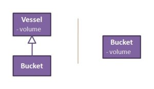
Moreover, a view contains more than just a subset of the objects of a model.  It can affect its relations as well. For example, a model containing a class vessel with an attribute volume and a subclass bucket (by generalization relation), may appear in a diagram as just the bucket class with the attribute volume in it. Notice that here, the view refers to the semantics of the modelling language.

Last but not least, views create redundancy, which affects modifiability. However, handling this kind of redundancy by separating object from presentation is the core capability of modelling tools. So, this can easily be solved by tools, as long as they are capable of handling the other aspects (‘sense’, semantics) of views.


All of the above properties – domain dependence of language, structured/ unstructured mix, broad audience, and the importance of views – are surely beneficial in software design models, too, but surely do not have such a prominent role there as they have in analysis.

So long,
|=

P.S.
Dear language and tool designers – do you think you’re fit for software analysis modelling?


Posted in Requirements, Software_Engineering | Tagged , , , , , , , , , , , , , | 2 Comments